Forage System Design
Four implements, one coordinated chain — why matching throughput capacities across the complete harvest system delivers more total output than optimising any single machine in isolation.
Most forage operations do not have a mowing problem or a baling problem. They have a system design problem — where one bottleneck implement limits the output of everything connected to it.
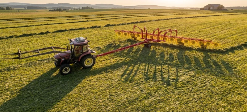
A hay operation is not a collection of individual machines. It is a production chain where the output of each implement becomes the input for the next, and where the weakest link in that chain determines the maximum throughput of the entire system — regardless of how capable the other machines are. A high-output round baler producing 80 bales per hour behind a mowing system that can only cut 1.5 ha/h will spend most of the day waiting for windrows. A wide-coverage mower conditioner cutting 3.2m per pass whose output is consolidated by a narrow-working rake that cannot keep up will leave cut crop in swath longer than the quality window allows. A baler running at full throughput on good windrows that relies on a loader and single-axle trailer for field clearance will eventually slow or stop when the field becomes congested with ejected bales.
Designing a forage harvest system means selecting and matching implements across the complete chain so that each stage can process the output of the stage before it at a rate that keeps the whole system moving without bottlenecks. This is straightforward in principle but frequently wrong in practice, because most equipment purchasing decisions are made one machine at a time — driven by the immediate need, the available budget at that moment, and the recommendation of the dealer who is selling that particular machine. The system perspective — asking how this machine will interact with what comes before and after it in the chain — is rarely the primary frame for an individual equipment purchase.
This guide covers the four-implement forage harvest chain — mower conditioner, rake, round baler, and bale transporter — and explains how to match their capacities to each other, how to calculate whether your current system has a bottleneck, and what the correct sequence of equipment investment looks like when building or upgrading a system from scratch. For the implements referenced throughout this guide, browse our complete range of forage harvesting equipment.
1. The Four-Stage Chain: What Each Implement Does and What It Hands to the Next
Stage 1 — Mower Conditioner: Converting Standing Crop to Conditioned Swath
The mower conditioner is the entry point of the harvest chain. It severs standing vegetation at the set stubble height and immediately conditions the cut material — crushing or abrading the stem cuticle — to accelerate moisture evaporation and reduce field drying time by 30–50%. What it hands to the next stage is a conditioned swath at the set width, at a certain material density per unit length, at a moisture content that will continue to decline through the field drying period. The mower conditioner’s throughput determines the maximum rate at which new material enters the system — the ceiling for everything that follows. Every subsequent stage either keeps up with that ceiling or becomes a bottleneck that forces cut crop to wait in swath longer than the quality window allows.
The key output specifications that flow from the mower conditioner to the rake are cutting width (which determines how wide a swath the rake must collect from), swath width setting (which determines the consolidation work the rake must perform), and conditioning effectiveness (which determines how much additional drying time the swath needs before reaching optimal raking moisture). A 3.2m mower conditioner set to a 2.0m swath producing 2.4–2.8 ha/h of conditioned material is a specific input load for the raking stage — the rake must be able to handle this at or above the mowing rate to avoid a windrow accumulation backlog.
Stage 2 — Rake: Converting Swath to Windrow
The rake’s function is to gather the conditioned swath left by the mower conditioner and consolidate it into a windrow of the width and density that the baler’s pickup can collect efficiently. The rake adds drying time to the crop — raking at the optimal moisture window (30–40% for grasses, 35–45% for legumes) turns and fluffs material to expose more surface area to sun and wind, accelerating the final drying phase. The windrow it produces hands to the baler a specific width, a specific material weight per unit length, and a consistent moisture content. The baler’s pickup width and throughput rate must match what the rake produces — a windrow wider than the pickup produces lateral loss; a windrow heavier than the baler can process at rated speed creates compression chamber surge.
Stage 3 — Round Baler: Converting Windrow to Stored Bale
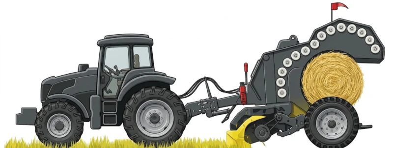
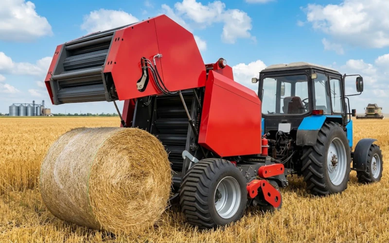
The round baler receives the windrow from the rake and compresses it into a bale at the target density, applies net wrap, and ejects the finished bale onto the field. Its throughput — measured in bales per hour and tonnes per hour — must match or exceed the rake’s windrow formation rate so that windrows do not accumulate unraked in front of the baler as the day progresses. The bale it produces hands to the transport stage a specific size, weight, and net wrap integrity — all of which determine how the bale transporter can handle it and what the storage outcome will be.
Stage 4 — Bale Transporter: Converting Field Storage to Managed Storage
The bale transporter collects finished bales from the field and moves them to the storage facility. Its throughput — determined by load capacity, field-to-storage cycle time, and loading and unloading speed — must be sufficient to clear bales from the field at the rate the baler produces them. If it cannot keep up, the field accumulates bales that block subsequent baling passes, create bale density inconsistency when the baler must steer around ejected bales on narrow windrow strips, and risk damage from field equipment and weather exposure. The transport stage is the most frequently underspecified element in forage harvest chain design, because its capacity constraint does not become visible until the baler has been running for several hours and the field starts filling with uncleared bales.
2. Capacity Matching: The Calculation Every System Designer Must Do
The system design calculation starts by identifying the production target — the total hectares to be harvested per cut, divided by the number of available working days in the typical weather window for your region — and working backward through the chain to determine what throughput rate each stage must achieve to meet that target without creating a bottleneck.
An Illustrative Capacity Example
Consider a 300 ha alfalfa operation with a 3-cut season. Each cut must be completed within a 4–5 day weather window to maintain quality. With two 8-hour working days available before weather risk rises significantly, the system must cut, rake, and bale 300 ha in 16 productive machine hours — a combined mowing rate of approximately 19 ha per working day, or 2.4 ha/h continuous throughput across the full system.
| Stage | Required Rate | Matched Implement | Rated Capacity |
|---|---|---|---|
| Mowing | ≥2.4 ha/h | 9GQY-3.2 Mower Conditioner | 2.4–2.8 ha/h ✓ |
| Raking | ≥2.4 ha/h | 9LZY-9.0 Finger-Wheel Rake | 7.2–9.0 ha/h ✓✓ |
| Baling | ≥60 bales/h | S9000 Classic Round Baler | 40–100 bales/h ✓ |
| Transport | ≥18 t/h cleared | 9JYY-4.5 Bale Transporter | 4500 kg/trip ✓ |
In this example, the mowing stage is the system’s natural rate-setter — the 9GQY-3.2 at 2.4–2.8 ha/h is operating near its capacity ceiling. The rake has substantial surplus capacity (7.2 ha/h versus the 2.4 ha/h required), meaning it can easily service the mower’s output without becoming a bottleneck. The baler at 40–100 bales/h has adequate throughput to keep up with the windrow volume from a single mower. The transport stage, at 4500 kg per trip with a 15-minute cycle time to storage, clears approximately 18 tonnes per hour — matching the baler’s output rate on 300 kg alfalfa bales at 60 bales/hour.
The bottleneck test: For each stage in your system, calculate its throughput rate in the same units (tonnes per hour or hectares per hour) and compare them. The lowest throughput stage is your system’s bottleneck — it limits the output of every upstream and downstream stage regardless of their individual capacity. Invest in eliminating the bottleneck before adding capacity anywhere else in the chain.
3. The Power Transmission Chain: Where System Reliability Actually Lives
A forage harvest system is not just a chain of field implements — it is a chain of power transmission connections, where every PTO-driven machine depends on a driveshaft that must reliably deliver the rated power input at the rated speed throughout the working day. The system’s mechanical reliability is only as good as the weakest power transmission link in the chain, and that link is almost always the PTO driveshaft rather than the implement itself.
Why PTO Shafts Are the Most Common System Failure Point
PTO driveshafts are the most mechanically stressed component in any trailed implement system: they transmit full engine power through rotating universal joints at operating angles that change with terrain, they telescope under the dynamic length changes that occur as the tractor-implement articulation angle varies through headland turns, and they absorb the overload events generated when the implement encounters unexpected resistance — a dense material slug, an embedded stone, a sudden blockage. They are also the component most commonly underspecified, because their specification requires matching the shaft’s torque rating to the implement’s peak load — not its average load — and peak loads in forage harvesting can be three to four times the steady-state average.
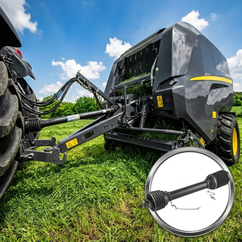
A correctly specified pto shaft for each powered implement in the harvest chain — rated for the peak torque of that implement at its operating speed, dynamically balanced, equipped with a correctly calibrated overload protection device, and maintained with intact full-length guarding — is the single most cost-effective reliability investment available for a forage harvest system. The cost of a correctly specified shaft is modest relative to the cost of the implement it protects. The cost of a shaft failure during a narrow harvest window — in downtime, in quality loss from crop left in swath, and potentially in implement damage from an under-protected overload event — is many times the cost of the shaft itself.
Shaft Specification by Implement Type in the Harvest Chain
Each powered implement in the harvest chain has different peak torque characteristics that determine the shaft specification required:
- Mower conditioner (9GQY-3.2): High peak torque from disc cutterbar contact with dense crop and occasional field debris. Requires a friction-clutch overload device that reconnects automatically — not a shear bolt that needs manual replacement after each overload event.
- Rake (ground-driven): The 9LZY-9.0 finger-wheel rake requires no PTO shaft — it is ground-driven. The 9LH-12 horizontal rake similarly requires no PTO drive. This eliminates one shaft from the system and one potential failure point.
- Round baler (S9000 / 9YG series): Moderate steady-state torque with periodic spikes from dense windrow sections and net wrap system engagement. Balance and smooth running at 720 r/min are as important as torque rating for sensor-controlled density system accuracy.
- Bale transporter (9JYY-4.5): The hydraulic system powers the loading arm — no PTO shaft required. The tractor’s hydraulic output capacity (minimum 16 MPa across two remote valve circuits) is the critical specification, not PTO torque.
4. Building the System in the Right Sequence
Most forage operations do not build their complete system at once — they add implements over multiple seasons as budget allows and as the operation’s scale grows. The sequence in which implements are added to a growing system significantly affects how much value each successive investment delivers, because adding an implement that does not eliminate the current bottleneck produces less productivity improvement than the implement’s individual specification suggests.
The Right Sequence for a Growing Hay Operation
Start with the baler — it is the value-creation step
The round baler is the implement that converts loose windrow material into a storable, transportable, sellable product. Before you have a baler, you have crop — with a baler, you have hay. Mowing can be done with a simple disc mower or even a rotary mower at small scale; raking can be contracted out; but the baler defines whether the operation is a hay operation or not. Select the baler first, based on your production target and tractor power, and build the rest of the system to feed it.
Add a mower conditioner matched to the baler’s throughput
Once the baler defines the system’s throughput target, select a mower conditioner whose rated capacity at normal working speed matches or slightly exceeds the baler’s consumption rate. For a baler producing 40–60 bales per hour on alfalfa, a 3.2m mower conditioner at 2.4–2.8 ha/h provides the right mowing rate to keep windrow supply consistent. Adding a wider mower conditioner than the baler can consume creates cut crop waiting in swath — not a capacity increase but a quality risk increase.
Add a rake with surplus capacity above mowing rate
The rake should always have more capacity than the mowing stage produces — because raking begins some hours after the mowing day starts (waiting for the optimal raking moisture window) and must therefore catch up to the accumulated swath area before the baler arrives. A finger-wheel rake with 7–9 ha/h capacity behind a 2.4 ha/h mower conditioner provides this comfortable surplus, ensuring the raking pass is complete and the windrows are correctly formed before the baler starts its pass.
Add a bale transporter sized to the baler’s daily output
Calculate your baler’s daily output in tonnes (bales per hour × bale weight × productive hours per day) and divide by the transporter’s payload per trip to determine minimum trips required per day. For the 9JYY-4.5 at 4500 kg per load and a baler producing 60 bales at 300 kg per hour for 8 hours (144 tonnes/day), the transporter must complete 32 trips per day. At a 15-minute round-trip cycle, this requires 8 hours of continuous operation — one transporter, one operator, fully committed. For operations with longer field-to-storage distances, two transporters may be needed to keep the baler from stalling on a congested field.
5. Common System Design Mistakes and How to Avoid Them
Mistake 1: Overinvesting in Mowing Capacity Before Baling Capacity
The most common system design mistake is buying a wide mower conditioner — attracted by its high coverage rate — without ensuring the baling stage can consume its output. A 5m mower conditioner producing 4–5 ha/h of cut material behind a baler rated for 2.5 ha/h consumption creates a growing swath backlog that requires the baler to rush its compression cycle to catch up, producing inconsistent bale density, or forces cut material to remain in swath until the next day when moisture and quality have changed. The mowing stage should not exceed the baling stage’s throughput by more than 20–30% in normal operation.
Mistake 2: Treating Field Clearance as an Afterthought
Operations that invest carefully in their mowing, raking, and baling stages but rely on a tractor-with-spike-and-single-axle-trailer for field clearance consistently find that field congestion limits baler productivity in the afternoon of a long baling day. The baler must steer around accumulating ejected bales, leaving windrow sections uncollected that require a second pass. The hydraulic bale transporter — at 4500 kg per load with one-operator hydraulic pickup — is the stage that protects the baler’s afternoon productivity and ensures the field is cleared to a condition that allows the next day’s mowing to start on a clean surface.
Mistake 3: Mismatching Windrow Width to Baler Pickup Width
The rake’s windrow width output must be set to match the baler’s pickup width — within 10–15% of pickup width for efficient single-pass collection. A windrow set at 2.0m for a baler with 1900mm pickup causes the baler to miss material at the windrow margins. A windrow set at 0.8m for a baler with 2240mm pickup leaves the chamber unfilled for the first part of each pickup pass, reducing the bale-per-hour rate and creating inconsistent density in the first bale layer. Before setting the rake’s windrow width, confirm the baler’s rated pickup width and set the rake to produce a windrow approximately 85–90% of that width.
Mistake 4: Running Multiple Implements on One Tractor Sequentially
Small operations where one tractor must serve as the mowing tractor, the raking tractor, and the baling tractor sequentially — disconnecting one implement and connecting the next — pay a significant time cost in implement changeover and lose the ability to run the mowing and raking stages simultaneously, which is usually the most time-efficient approach for operations with access to a second tractor. If operating with one tractor is the constraint, the sequence that minimises quality risk is: mow the complete field first, allow the swath to reach raking moisture, rake the complete field, allow windrows to reach baling moisture, then bale — treating the harvest as a three-day sequential operation rather than a simultaneous coordinated system.
Designing or Upgrading Your Forage Harvest System?
Whether you are building a complete four-implement chain from scratch or identifying the bottleneck in an existing system, our technical team can help you calculate the capacity match across every stage and select the implements that eliminate your current constraint.