9F-70 Forage Crusher
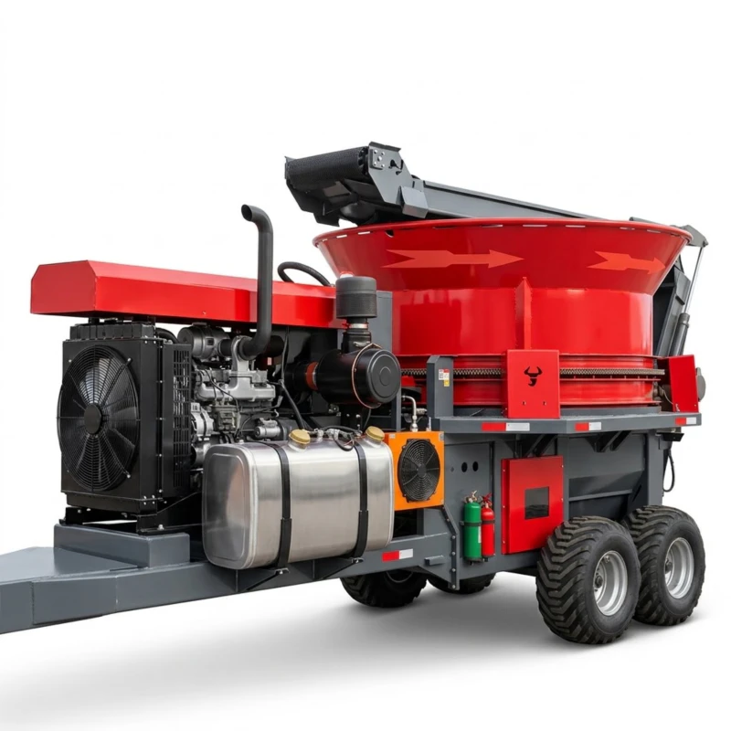
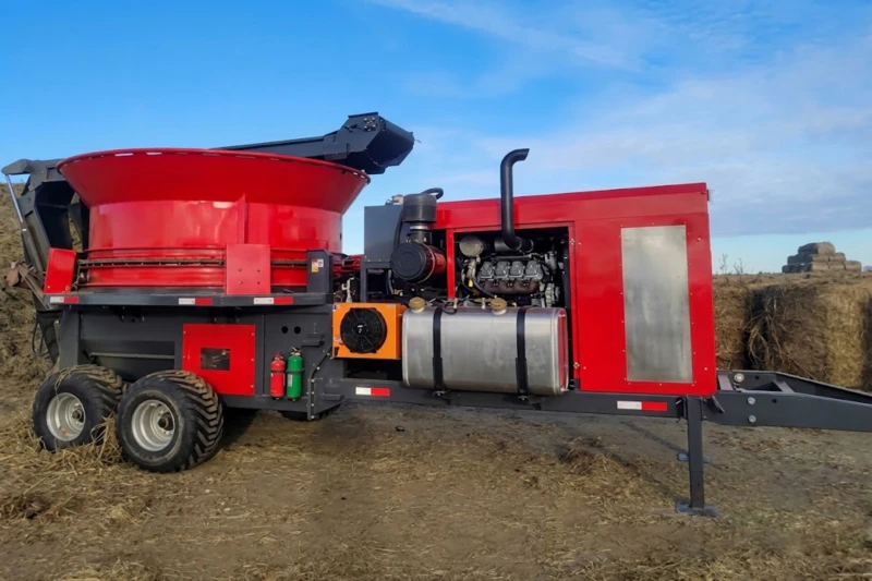
9F-70 Forage Crusher — 84-hammer locked rotor, 728mm dia., 1255mm crushing width, 44 blades, disc-cycle feeder. Diesel or electric. Stationary TMR straw feed processing.
9F-70 Forage Crusher: High-Capacity Stationary Hammer-Knife Processing for Commercial Feed Production and Straw Utilization
84 hammer knives across a 728mm rotor, 1255mm crushing width, 450mm intake diameter, disc-cycle feeding system, and 1690 r/min output shaft speed — a stationary floor-mounted platform designed for continuous commercial-scale forage crushing, straw processing, and mixed feed preparation.
1. Introduction: The Role of Forage Crushing in Commercial Feed and Straw Utilization
Whole-stalk forage and baled crop residue in unprocessed form has limited feed value for livestock: the intact stem structure resists rumen breakdown, reducing digestibility and the proportion of available energy and protein that animals can extract from the material. Mechanical crushing disrupts the fibrous stem wall, breaks internode structure, and reduces particle size to the range where rumen microorganisms can access the plant cell contents efficiently. The improvement in feed conversion from crushed versus uncrushed forage is measurable in animal performance: dairy herds fed crushed alfalfa consistently show higher dry matter intake and milk yield compared to herds fed the same crop in long-chop form, because reduced particle length accelerates rumen passage rate and allows higher total daily feed intake.
Beyond pure livestock feed applications, forage crushing is the first processing step for straw-to-substrate preparation for edible mushroom cultivation, straw-to-biomass densification for energy applications, organic fertiliser incorporation programs, and mixed total mixed ration (TMR) preparation in commercial dairy and feedlot operations. In all these applications, the throughput capacity and consistency of the crushing machine determine the processing station’s overall productivity — a limitation in the crusher becomes a limitation for the entire downstream operation. The 9F-70 Forage Crusher is engineered as a stationary commercial-scale processing platform with the capacity, structural robustness, and operational reliability that continuous-duty commercial feed processing requires. For the field equipment that produces and transports the bales this machine processes, explore our complete round baler and forage harvesting equipment range.
The 9F-70’s stationary floor-mounted design reflects the operational reality of commercial feed processing: unlike field implements that must be compact and mobile, a stationary crusher can be optimised for capacity and robustness without the weight and dimension constraints of tractor-trailed equipment. At 2300 kg with overall working dimensions of 7700 × 3080 × 2900mm, the 9F-70 is a permanent installation for a feed preparation facility, barn processing area, or dedicated straw utilization station — a capital investment that delivers per-tonne processing cost reduction across thousands of operating hours over its service life.
2. Working Principle: Disc-Cycle Feeding and Hammer-Knife Rotor Crushing
Disc-Cycle Feeding System
Material enters the 9F-70 through the 450mm diameter intake via the disc-cycle feeding system. The disc-cycle mechanism uses a rotating disc arrangement that draws material progressively into the crushing chamber in a continuous, even flow — rather than the surge-and-gap feeding pattern that reciprocating or auger systems produce when material density is uneven. This continuous feeding characteristic is the disc-cycle system’s primary operational advantage: the hammer-knife rotor receives a consistent material volume per revolution, maintaining stable power draw and consistent particle size distribution throughout the processing session. When material supply is temporarily interrupted or density drops between loads, the disc cycle continues rotating, preventing the rotor from encountering a sudden heavy slug of material when feeding resumes — the sudden-load event that most commonly causes overload trips in continuous-duty crusher applications.
84-Hammer Locked-Rotor Crushing
The core crushing mechanism of the 9F-70 is its 728mm diameter hammer-knife rotor carrying 84 individual hammer elements. The rotor operates at 1690 r/min output shaft speed, giving the hammer tips a peripheral velocity of approximately 64 metres per second — the impact velocity that delivers the impact energy needed to fracture dry forage stems, crush internode joints, and reduce material to the target particle size range in a single rotor pass. The locked rotor design — where hammer elements are fixed rather than free-swinging — concentrates the full rotor mass inertia into each impact event rather than allowing the hammer to partially absorb impact energy through rotation about its pivot pin. This locked architecture delivers higher impact energy per hammer-material contact, enabling effective crushing of tough, dry crop stalks that would require multiple passes in a free-hammer design at equivalent rotor speed.
The 1255mm crushing width accommodates material across the full processing zone, ensuring that wide-load material entering through the 450mm intake is spread across the rotor length without the lateral concentration that creates uneven wear patterns and rotor imbalance over time. With 84 hammers distributed across the 1255mm rotor width — approximately one hammer per 15mm of rotor width — every segment of the material stream entering the crushing zone encounters hammer contact within each rotor revolution, producing consistent particle size reduction without the coarse-particle fraction that appears when material passes through gaps between widely spaced hammers.
44-Blade Screen and Particle Size Control
The 44 blades working in coordination with the rotor hammers provide the secondary size reduction and particle sizing function that determines final product particle length. After hammer impact reduces material to sub-threshold dimensions, the blade-and-screen combination controls the maximum particle size that exits the crushing zone — material that has not reached the target particle size remains in the crushing zone for additional hammer contact until it passes through the screen aperture. Blade selection and screen aperture size can be matched to specific processing applications: finer screens and tighter blade clearance for applications requiring short particle length (dairy TMR, mushroom substrate), coarser configuration for applications where longer particle length is acceptable (biomass densification, bedding preparation).
The 84-hammer count at 1690 r/min means that at 64 m/s tip speed, each point in the material stream entering the crushing zone encounters a hammer impact at a frequency exceeding 2,000 impacts per second. This impact frequency is what produces consistent particle size distribution rather than the bimodal distribution (some material very fine, some material still coarse) that lower hammer count rotors produce. Consistent particle size matters commercially because feed mixing quality — the uniformity with which different feed ingredients are blended in a TMR — depends on all ingredients being in a similar particle size range. Oversize particles segregate from the mix during transport and delivery, causing inconsistent nutrition across the feedbunk. The 9F-70’s high hammer density at commercial rotor speed produces the narrow particle size distribution that TMR mixing quality requires. For supporting field equipment, visit our complete forage equipment catalogue.
3. Complete Technical Specifications
The following table contains the engineering specification sheet for the 9F-70 Forage Crusher, transcribed from factory documentation. All values reflect standard operating conditions at rated power input.
| No. | Item | Unit | Parameter |
|---|---|---|---|
| 1 | Model Name | / | 9F-70 Forage Crusher |
| 2 | Structure Form | / | Stationary Operation |
| 3 | PTO Drive | / | Stationary (floor-mounted) |
| 4 | Power Type | / | Diesel / Electric Power |
| 5 | Rated Power of Built-in Engine | kW | 181 |
| 6 | Rotor Manufacturing Type | / | Locked Type |
| 7 | Rotor Cutter Type | / | Hammer Knives Type |
| 8 | Hammer Quantity | pcs | 84 |
| 9 | Intake Diameter | mm | 450 |
| 10 | Rotor Finishing Diameter | mm | 728 |
| 11 | Blade Quantity | pcs | 44 |
| 12 | Crushing Width | mm | 1255 |
| 13 | Overall Dimensions (L×W×H) | mm | 7700 × 3080 × 2900 |
| 14 | Power Output Shaft Speed | r/min | 1690 |
| 15 | Productivity | t/h | 2300 (see note) |
| 16 | Standard Weight | kg | 2300 |
| 17 | Feeding Method | / | Disc Cycle Feeding System |
4. Five Core Advantages
Advantage 1: Locked-Type Hammer Rotor for Maximum Impact Energy per Strike
The locked-type rotor design is the 9F-70’s defining mechanical advantage over conventional free-hammer forage crushers. In a free-hammer design, each hammer element pivots about a pin under impact, absorbing a portion of the impact energy through rotation and reducing the kinetic energy transferred to the material being crushed. The locked design eliminates this energy absorption mechanism: each hammer element is fixed rigidly to the rotor body, so the full rotational inertia of the rotor is available for each impact event. At 1690 r/min with a 728mm rotor, this locked-inertia impact energy is substantially higher per impact than an equivalent free-hammer design at the same speed — enabling effective single-pass crushing of tough dry stalks that free-hammer designs would require multiple passes to reduce to equivalent particle size. For commercial operations where throughput rate is the primary economic metric, higher impact energy per pass means higher processing rate per unit of installed power.
Advantage 2: 84-Hammer High Density for Consistent Particle Size Distribution
With 84 hammer elements across the 1255mm rotor width, the 9F-70 achieves an average hammer spacing of approximately 15mm — ensuring that every point in the material stream entering the crushing zone receives multiple hammer impacts per second. This high hammer density produces the narrow particle size distribution (most particles close to the target size, few outliers) that is the quality requirement for commercial feed mixing and substrate preparation. Compared to lower hammer-count rotors of equivalent width where hammer spacing exceeds 30–40mm, the 9F-70 produces significantly fewer oversize particles that would need to be re-circulated or would cause feed sorting problems in the downstream application. This particle size consistency translates directly into commercial value: uniform particle size TMR feed has less sorting at the feedbunk, less nutritional variability between animals, and more predictable animal performance outcomes.
Advantage 3: Disc-Cycle Feeding for Continuous, Surge-Free Processing
Commercial-scale forage crushing operations face the practical challenge of feeding material from bales, bulk windrow loads, or manual delivery into the crusher at a consistent rate throughout the working session. Material delivered manually or from loader bucket drops tends to arrive in uneven surges — a large slug of material followed by a gap while the next delivery is prepared. Crusher designs that handle surge feeding poorly — overloading, tripping breakers, or producing large oversize particle fractions during the heavy surge — slow down commercial operations more than their rated capacity suggests, because the downtime from trip recovery and the quality loss from surge processing accumulates across a working day. The disc-cycle feeding system mitigates this problem by acting as a buffer and metering device between the material delivery point and the crushing zone, absorbing delivery surges and presenting consistent material volume to the rotor throughout the operating cycle.
Advantage 4: Diesel or Electric Power Flexibility for Diverse Installation Contexts
The dual power type specification — diesel or electric — allows the 9F-70 to be installed in processing environments with or without access to high-capacity electrical infrastructure. In established dairy farms and feed mills with three-phase electrical supply, electric motor drive provides quiet, low-vibration operation with no exhaust emissions in enclosed buildings, simple speed control, and lower running cost per hour than diesel. In remote locations, temporary processing sites, or farms where three-phase electrical supply is unavailable or insufficient for the rated power demand, diesel engine drive provides full independence from grid infrastructure. The option to select power type at installation allows the 9F-70 to serve the widest possible range of commercial processing contexts without requiring infrastructure upgrades that would add cost and delay to commissioning.
Advantage 5: Stationary Design for Continuous-Duty Commercial-Scale Processing
The 9F-70’s stationary floor-mounted design reflects an engineering philosophy that optimises for processing capacity and long-term structural durability rather than portability. At 2300 kg with the structural frame, rotor, feeding system, and drive components sized for sustained continuous-duty operation, the 9F-70 provides robustness margins that mobile or semi-portable crushers cannot match within their transport weight constraints. The robust bearing sizes, heavy-section frame members, and industrial-grade component specifications suited to 24-hour or extended operating cycles are achievable in a stationary platform precisely because weight is not a constraint. For commercial feed mills, large dairy operations, and straw processing facilities where the crusher operates for multiple hours per day across years of service life, this structural robustness is the primary determinant of total cost of ownership — the reduction in repair frequency and downtime that heavy-duty construction provides compounds into significant cost savings versus lighter-built alternatives over a five-to-ten-year service horizon.
5. Commercial Application Scenarios
Commercial Dairy and Livestock TMR Feed Preparation
Total mixed ration preparation requires that all forage ingredients — hay, alfalfa, straw, silage — be processed to compatible particle size ranges before mixing, so that the mixed ration maintains uniform composition from mixer loading to feedbunk delivery without sorting. Long-chop or baled forage with highly variable particle length causes sorting both in the mixer wagon and in the feedbunk, leading to nutritional inconsistency between animals and between feeding events. The 9F-70’s consistent particle size output directly addresses this quality requirement. For large dairy operations processing 20–50 tonnes of dry forage per day for herd feeding, the 9F-70’s stationary processing capacity, continuous-duty design, and consistent output particle size make it the appropriate scale of investment for this application.
Straw Substrate Preparation for Edible Mushroom Cultivation
Wheat straw substrate for oyster mushroom and related edible fungus cultivation requires crushing to a specific particle length range — typically 3–8cm — that supports optimal mycelium colonisation rates while maintaining adequate porosity for gas exchange during incubation. Particle lengths outside this range reduce yield: overly long particles colonise slowly, reducing substrate throughput; overly fine particles compact during sterilisation, reducing oxygen penetration. The 9F-70’s adjustable blade and screen configuration allows targeting of the specific particle length range for the cultivation species involved. At the scale of commercial mushroom substrate operations processing tonnes of straw per day, the 9F-70’s continuous-duty capacity and consistent output directly determine the operation’s annual production capacity.
Biomass Pre-Processing for Densification and Energy Applications
Straw and forage biomass for pelletisation, briquetting, or direct combustion in biomass boilers requires size reduction before the densification process — pellet and briquette dies require material with maximum particle lengths typically below 30–50mm to achieve consistent die fill and product density. The 9F-70 performs this primary size reduction step, receiving baled or loose straw from the round bales collected by the 9JYY-4.5 bale transport system, and processing it to the particle size required by the downstream densification equipment. The stationary installation at the processing facility allows a coordinated material flow from field baling through transport to the 9F-70 crusher and on to the densification line — a complete straw-to-biomass-product chain that the 9F-70 anchors at the processing station.
Organic Fertiliser and Soil Amendment Production
Crop straw incorporated into soil or compost as an organic amendment breaks down most effectively when pre-crushed to short particle lengths that maximise surface area for microbial attack. Whole or minimally processed straw incorporated directly into compost windrows or soil creates nitrogen immobilisation and slow decomposition that delays nutrient release. The 9F-70 processes straw to the short-particle length that accelerates composting decomposition rates and improves mixing uniformity in compost turning operations — reducing the composting cycle time and improving the nutrient availability of the finished compost product.
6. Integration with the Complete Forage Production and Processing Chain
The 9F-70 Forage Crusher operates at the end of the forage production chain that begins in the field. Understanding the complete chain allows feed processing facility operators to specify the right capacity and configuration at each stage:
For system design advice matching your specific field area, daily production volume, and downstream processing requirements, contact our technical team for a complete chain capacity analysis.
7. Power Transmission and Drive System Considerations
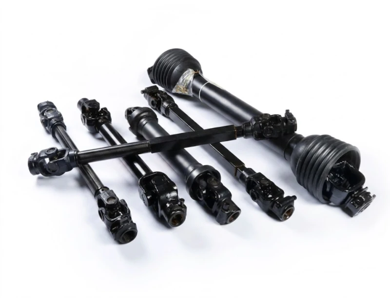
The 9F-70 is a stationary machine powered by a built-in engine or electric motor rather than a tractor PTO. However, the forage production chain that supplies material to the 9F-70 includes PTO-driven field implements — the mower conditioner and round balers — that require properly specified driveshafts for safe and efficient operation. When designing or operating a complete forage production and processing system, every powered link in the chain must be correctly specified. For PTO-driven field equipment pairing with the 9F-70 processing station, a correctly rated pto shaft matched to each implement’s power and speed specification is essential for system uptime and safety.
9F-70 Direct Drive and Electrical Installation Requirements
For electric motor drive installations, the 9F-70 requires a three-phase electrical supply adequate for the rated power at startup and running load. Crusher motors draw 2–3× running current at startup — the installation wiring, fusing, and motor starter must be rated for the startup surge, not just the running current. Consult a qualified electrical contractor for installation design. Ensure the motor starter includes appropriate overload protection that trips the motor before thermal damage occurs during blockage events, but does not false-trip during normal heavy-load processing periods.
For diesel engine drive installations, ensure adequate ventilation for exhaust emissions if the crusher is installed in an enclosed barn or processing building. Position the exhaust outlet to direct combustion gases away from operating personnel and away from feed products being processed. Service access to the engine’s oil, fuel, and air filter systems must be maintained clear even after the crusher is permanently installed in its operating position.
8. Manufacturing Quality and Long-Term Reliability
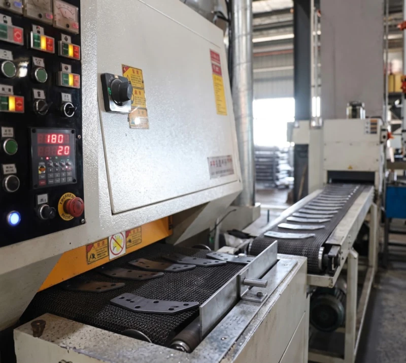
The 9F-70 operates under sustained high-load conditions that are among the most mechanically demanding in agricultural processing equipment: a 728mm rotor at 1690 r/min, 84 hammers each impacting tough dry material hundreds of times per second, and a continuous feeding system delivering material without rest periods. The structural, material, and balance specifications that maintain reliable operation under these conditions are established during manufacturing, not correctable through maintenance alone.
9. Frequently Asked Questions (FAQ)
The 9F-70 is designed for dry forage and straw processing: alfalfa hay, grass hay, wheat straw, rice straw, corn stover, soybean straw, and similar dry agricultural residues. Material should be at a moisture content below approximately 20% for efficient hammer-impact crushing — high-moisture material absorbs impact energy and passes through the crushing zone without adequate size reduction, clogging the screen and reducing throughput. For high-moisture silage or fresh forage processing, a different machine type (wet forage chopper or green-feed cutter) is more appropriate.
Output particle size is primarily controlled by screen aperture size — a finer screen retains material in the crushing zone longer, resulting in smaller average particle size at the cost of lower throughput rate. Secondary adjustment is available through blade clearance settings that control the gap between the counter-blades and the rotor hammers, affecting the secondary shear-cutting action that further reduces particle size in the screen zone. For specific particle size requirements for your application, consult our technical team for screen and blade configuration recommendations matched to your material type and target particle specification.
The electric drive configuration requires a three-phase electrical supply rated for the motor’s nameplate power plus startup current surge. A qualified electrical contractor should design the installation wiring, distribution board, motor starter, and earthing system specific to the installation site. The rated power figure should be confirmed from the motor nameplate on your specific unit before commencing electrical installation design — contact our technical team for the precise motor specification for the electric drive variant.
Follow this mandatory sequence: (1) Shut down power (motor off or diesel stopped). (2) Apply lockout/tagout — physically lock the power isolator in the off position and remove the key. (3) Wait for the rotor to come to a complete stop — do not use a brake or physical contact to stop it faster. (4) Confirm complete stop by observing the rotor for a minimum of 30 seconds without any movement. Only then open the crushing chamber access for hammer or blade inspection and replacement. Reinstall all guards and confirm all fasteners are torqued to specification before starting. Never reach into the crushing zone with the power connected, even if the machine appears stationary — stored rotor inertia can cause unexpected restart movement.
Daily: inspect hammer and blade condition for wear, chipping, or deformation before startup; check bearing housing temperatures after 30 minutes of operation (elevated temperature indicates lubrication deficiency or bearing damage); clear any material accumulation from the screen before shutdown. Every 50 hours: grease all bearing lubrication points; check drive belt tension and condition (if belt-drive configured); inspect rotor housing interior for wear liner condition. Every 200 hours: measure hammer wear against the minimum thickness specification; replace hammers in matched sets to maintain rotor balance; inspect screen apertures for enlargement from wear; check disc-cycle feeding mechanism bearing condition.
Metal object ingestion is the most serious operational risk in forage crushing. A piece of baling wire, a metal spike, or a bolt fragment entering the crushing zone at 1690 r/min rotor speed can damage hammers, fracture counter-blades, and create projectile fragments that exit the machine at high velocity — causing equipment damage and serious safety risk to nearby personnel. Install a magnetic separator on the infeed to intercept ferrous metal before it reaches the rotor. Inspect all material loads for visible metal contamination before feeding, and stop immediately if abnormal metallic sounds are heard during operation. After any confirmed metal ingestion event, inspect all hammers and blades for damage before resuming operation.
The 450mm intake diameter is sized for material that has been loosened from bale form — not for whole intact round bales which range from 1000–1400mm in diameter, far exceeding the intake opening. Whole bales must be net-wrap removed and broken open before feeding to the 9F-70. A bale handler or net-wrap removal system positioned ahead of the 9F-70 infeed, or manual bale opening with a loader spike, prepares material for infeed at the rate the crusher can accept. For system layout advice combining the 9JYY-4.5 bale transporter, bale opener, and 9F-70 crusher into an efficient processing station, contact our technical team.
Complete Your Forage Processing Chain with the 9F-70
The 9F-70 Forage Crusher brings commercial-scale hammer-knife processing to your feed preparation facility — 84-hammer locked rotor at 1690 r/min, 1255mm crushing width, disc-cycle feeding, and diesel or electric power options. The stationary platform that converts baled forage into precision-size feed ingredients for TMR mixing, substrate production, and biomass processing.