
Technology Explained
Sensor density is not a premium feature for large operations — it is the engineering solution to a fundamental problem that manual pressure settings cannot solve: the bale you want is not the bale your field conditions produce without active feedback control.
Manual pressure adjustment tells the baler what to try. Sensor-controlled density tells the baler what to achieve — and keeps adjusting until it does, regardless of what the windrow presents.
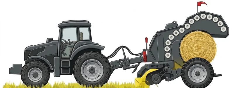
The phrase “sensor-controlled bale density” appears in baler specifications from multiple manufacturers in slightly different forms — intelligent density control, automatic pressure management, electronic density monitoring — but they all describe the same underlying engineering architecture: a real-time feedback loop that continuously monitors the compression force inside the baling chamber and adjusts the compression mechanism to maintain a target density setpoint, rather than holding a fixed hydraulic pressure setting and hoping that the variable conditions of commercial baling stay close enough to the design point that the result is acceptable.
Understanding what this architecture actually does — and why it outperforms manual pressure adjustment in every commercial hay scenario — requires understanding two things: why manual pressure settings produce variable results on consistent-seeming windrows, and what the sensor system measures that manual settings cannot respond to. These are not abstract engineering questions. The answers directly explain why two balers with the same model designation but different density control systems produce different bale weight consistency at the end of a commercial working day — and why that consistency difference translates into real financial outcomes through transport cost, export specification compliance, and storage quality.
This article explains the sensor density system from first principles, covering the measurement mechanism, the feedback control loop, the practical performance difference versus manual pressure, and the operational variables that affect how well any density control system — manual or sensor — can achieve its target. For the balers with sensor-controlled density systems this article discusses, see our range of commercial round balers.
1. Why Manual Pressure Settings Produce Variable Density — Even on Consistent-Looking Windrows
The Three Variables a Pressure Setting Cannot Compensate For
A manual hydraulic pressure setting in a round baler tells the system to resist bale expansion with a fixed force — the same force in the morning as in the afternoon, on dense windrow sections as on sparse ones, at high working speed as at reduced speed through headland turns. This fixed-force approach would produce consistent bale density if three variables remained constant: the volume of material entering the chamber per unit of bale rotation, the material’s resistance to compression, and the baler’s forward speed. In practice, all three vary continuously across a commercial baling day, and none of them varies in a predictable pattern that an operator could compensate for by adjusting the pressure setting at intervals.
Windrow density variation: Even a carefully raked windrow has density variation of 25–40% between its thinnest and densest sections — caused by variations in crop yield across the field, windrow overlap at field ends, the effects of combine or swather speed variation on swath thickness, and material displacement by wind between mowing and raking. A 30% windrow density variation at a fixed chamber pressure produces approximately 15–20% bale density variation — bales from the dense sections are significantly heavier than bales from the sparse sections, even though the pressure setting did not change between them.
Moisture variation across the day: Crop moisture at 8am in morning dew conditions may be 20–22%. The same windrow at 2pm in afternoon sun may be 12–14%. Material at 20% moisture has higher hydraulic resistance in the cell structure and compresses less efficiently under the same pressure than material at 14% moisture — the dry afternoon crop packs 25–30% more densely under the same force than the morning crop. A fixed pressure setting produces light bales in the morning and dense bales in the afternoon, on the same windrow, from the same field, with the same operator.
Forward speed variation: Baler working speed through headlands, around obstacles, and in variable crop density sections changes the material feed rate to the chamber — the volume per unit time that the compression system must process. At lower speed, the chamber receives less material per second; at higher speed, more. A fixed pressure setting does not adjust to these feed rate changes, producing bale layers of different compression density at different working speeds.
What the Density Distribution Looks Like in Practice
In controlled field testing on mature alfalfa with representative field conditions (25–35% windrow density variation, moisture declining from 19% to 13% across the working day, working speed variation of ±20% between headlands and mid-field), a manual-pressure baler set to produce 175 kg/m³ average density produced a distribution ranging from 131 kg/m³ to 214 kg/m³ — a spread of 83 kg/m³ around the target. Approximately 20% of bales were below 150 kg/m³ (failing a typical export specification floor) and 15% were above 195 kg/m³ (over-compressed and potentially causing bale structure distortion). Only 65% of bales were within ±15% of the target density despite the pressure being set to hit that target. This is not an operator failure or a baler failure — it is the predictable result of a fixed-setpoint system operating against variable conditions.
2. How Sensor-Controlled Density Works: The Measurement and Feedback Architecture
What the Sensors Measure
The core measurement in a sensor density system is the force applied to the bale’s outer surface by the compression elements — rollers, drums, or belt — at the current moment in the bale formation cycle. Pressure transducers (force-measuring sensors) mounted at the hydraulic cylinders that control the compression element positions report the current compression force in real time, typically at sampling rates of 10–50 measurements per second. This measured force, combined with the known geometry of the compression chamber and the bale’s current diameter (tracked by the system’s control unit from the initial material entry to the current rotation count), allows the control system to calculate the current bale density at every point in the formation cycle — not just at the end when the bale is ejected.
This continuous density tracking is the key difference from manual systems. A manual pressure system measures one variable — hydraulic pressure — and maintains it at a setpoint. A sensor system measures the outcome variable — actual density — and adjusts the hydraulic pressure to maintain the density setpoint, changing the pressure as needed to compensate for the material, moisture, and speed variables that manual settings cannot respond to. The pressure at 8am on wet morning alfalfa will be different from the pressure at 2pm on dry afternoon alfalfa — but the bale density will be the same, because the system is controlling density directly rather than pressure indirectly.
The Feedback Control Loop
The sensor density system operates as a closed feedback loop: measure current density → compare to target → calculate required adjustment → apply hydraulic pressure change → measure new density → repeat. This cycle operates continuously throughout the bale formation process — typically completing 5–15 adjustment cycles per second at normal working speeds. The result is that density deviations from the target are corrected within seconds of occurring, before they accumulate into a measurable bale-level density error. A windrow density spike that would cause a manual-pressure baler to over-compress 3–4 bale layers before the operator notices and adjusts the setting is corrected by the sensor system within the first 1–2 layers, so the finished bale shows negligible density variation at the layer level even when the incoming windrow was highly variable.
The response speed advantage in numbers: A manual-pressure system that an operator monitors and adjusts once every 10 minutes allows 10 minutes of density deviation to accumulate before correction — typically 25–40 bales at commercial baling rates. A sensor system that adjusts 10 times per second corrects density deviations within 1–2 bale layers — approximately 0.1% of the bale’s total mass. The difference in accumulated error between these two correction intervals explains why the density distribution width is 80–90% narrower under sensor control than under manual pressure management.
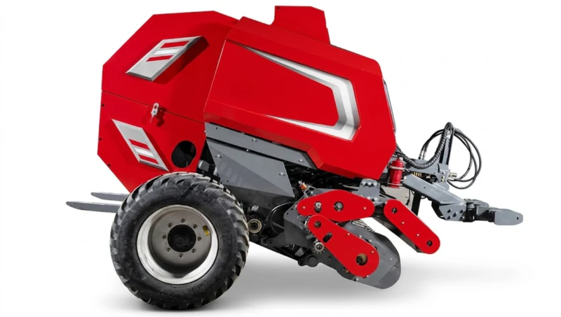
3. The Performance Difference: What the Numbers Show
Field Test Comparison on the Same Alfalfa Field
In the same field test conditions described in Section 1, a sensor-controlled density baler set to 175 kg/m³ target produced a distribution from 168 kg/m³ to 183 kg/m³ — a spread of just 15 kg/m³, compared to 83 kg/m³ for the manual system. Zero bales fell below the 150 kg/m³ export specification floor. The full production run was within ±4% of the target density — versus ±25% for the manual system. Individual bale weights were consistent within ±5 kg of the target weight across the full working day, including the morning wet period and the afternoon dry period that caused the manual system’s largest density swings.
The sensor system achieved this consistency by automatically increasing hydraulic pressure during the wet morning baling (to achieve the target density despite the reduced material compressibility) and reducing pressure during the dry afternoon (to prevent over-compression when material packed more efficiently). The pressure adjustments were continuous and automatic — the operator set the 175 kg/m³ target at the start of the morning, and the system maintained it without further intervention across a full 10-hour baling day that included two crop moisture transitions, three different windrow density sections, and multiple speed changes through headlands and field obstacles.
The Commercial Value of the Consistency Difference
| Performance Metric | Manual Pressure | Sensor Control |
|---|---|---|
| Density distribution width | ±25% (83 kg/m³ spread) | ±4% (15 kg/m³ spread) ✓ |
| Bales below export floor | ~20% of production | 0% ✓ |
| Operator adjustment needed | Multiple times per day | Set once per day ✓ |
| Bale-to-bale weight variation | ±30–50 kg per bale | ±5 kg per bale ✓ |
| Morning/afternoon density shift | Significant — operator-dependent | Eliminated by auto-adjustment ✓ |
Translating these performance differences into financial outcomes for a commercial operation producing 2,000 bales per season at 300 kg target weight and USD 150 per tonne hay value: the 20% below-floor rejection rate of the manual system represents 400 bales per season that would either fail export inspection (triggering price penalties) or require domestic sale at discount pricing. At a conservative USD 15 per bale price difference between export-grade and below-floor product, this is USD 6,000 per season in avoided price penalties from sensor control alone — before accounting for transport efficiency improvements from more consistent bale weight, or the operational efficiency of not manually monitoring and adjusting pressure throughout the day.
4. What Limits Sensor System Performance — and How to Stay Within Those Limits
Limit 1: The Hydraulic System’s Adjustment Speed
Every sensor density system has a maximum rate at which it can change the compression force — constrained by the hydraulic flow rate to the compression cylinders and the mechanical response time of the compression elements. When windrow density changes faster than this maximum adjustment rate — an abrupt transition from a thin gap to a very dense slug at the windrow junction from two heavy swaths merging — the sensor system cannot keep up with the change and the affected bale layer receives either too little or too much compression before the system catches up. The practical manifestation is a density outlier at the point of the abrupt transition that is within the system’s correction range but slightly above or below the target before settling back to the target density after 2–5 layers.
This limit is inherent to all sensor systems regardless of sophistication — it reflects the physics of hydraulic actuation rather than sensor or software quality. It is minimised by: consistent raking practice that avoids very abrupt windrow density transitions; working speed management that reduces the volumetric change rate presented to the chamber during transitions; and selecting a sensor system with the highest published hydraulic response rate available for the baler class. It does not significantly affect the bale-level density consistency that determines commercial outcomes — even with transition-point density variation, sensor systems produce far tighter bale-level consistency than manual alternatives.
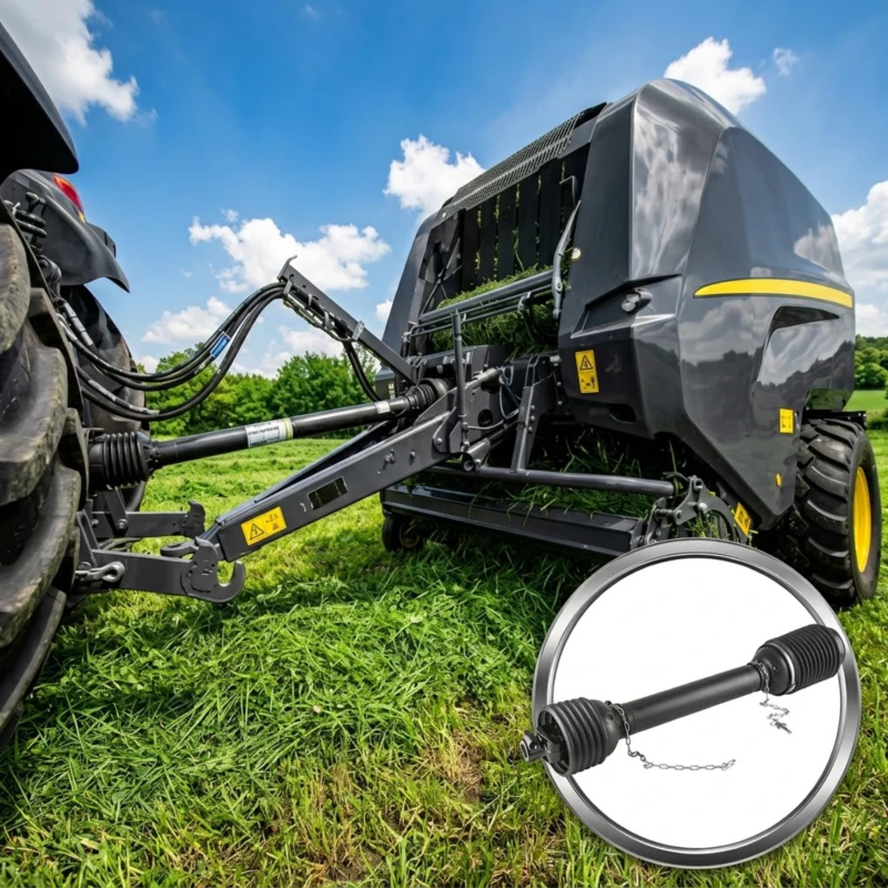
Limit 2: The PTO Shaft as a Measurement Noise Source
The sensor system’s pressure transducers measure hydraulic pressure in the compression cylinder circuit — a measurement that is affected by the mechanical load from the compression elements, which is in turn affected by the PTO-driven rotational speed of the chamber drums. If the PTO speed is not perfectly stable — because the tractor is under varying load, or because a worn or imbalanced pto shaft introduces speed variation — the pressure reading at the transducer fluctuates for reasons unrelated to bale density. The control system cannot distinguish PTO-speed-induced pressure variation from material-density-induced pressure variation, so it responds to both — making density adjustments in response to PTO speed noise as well as real density changes. The net result is increased density variation compared to the same sensor system operating with a stable PTO input.
This is the most practically important maintenance interaction between PTO shaft condition and sensor density performance. Producers who notice their sensor baler producing more density variation than expected — without any obvious change in crop type, moisture, or windrow quality — should inspect the PTO shaft’s universal joint bearing play and balance condition before investigating the sensor electronics. A shaft that introduces 2–5% speed variation at 720 r/min is sufficient to produce 10–15 kg/m³ of additional density variation in a sensor system that would otherwise maintain ±8 kg/m³ around the target. Replacing a worn shaft typically costs USD 300–600 and restores the sensor system’s rated density performance without any electronics repair or recalibration.
Limit 3: Calibration Drift and Seasonal Verification
Sensor density systems maintain their setpoint accuracy only as long as the pressure transducers are providing accurate readings relative to the calibration established at the factory or last service. Transducer drift — a slow change in the zero offset or sensitivity of the pressure sensor over time — causes the system to maintain a pressure that is correct according to its (drifted) measurement but produces a density slightly above or below the intended target. This drift is slow — typically less than 1–2% per season — but compounds over multiple seasons without recalibration into measurable density offset. A simple verification at the start of each season — weighing 10 consecutive bales on a calibrated scale and confirming the average weight matches the expected weight for the set density at the bale dimensions — identifies any calibration drift and allows the system to be recalibrated before the seasonal production begins.
5. Setting the Density Target: How to Choose the Right Setpoint for Your Crop and Market
A sensor density system’s primary operator interaction is setting the target density — the value the system will maintain regardless of field conditions. Choosing the correct target requires balancing three considerations: the crop’s physical compressibility limit at baling moisture, the buyer or market’s minimum specification, and the baler’s compression system capacity at the operating PTO speed.
Crop-Specific Target Ranges
Different crops have different maximum achievable densities at their optimal baling moisture — a ceiling set by the crop’s fibre structure and cell water content. Attempting to set a target above this ceiling causes the compression system to operate at maximum hydraulic pressure continuously without achieving the target, degrading bale shape and accelerating compression element wear without producing the desired density. The following reference ranges represent practically achievable targets at optimal moisture for common hay crops:
Premium alfalfa (14–16% moisture): 160–200 kg/m³ achievable; typical export target 170–185 kg/m³
Grass hay, ryegrass, mixed sward (14–18% moisture): 140–175 kg/m³ achievable; domestic market target 145–165 kg/m³
Wheat or rice straw (12–15% moisture): 115–160 kg/m³ achievable; biomass buyer minimum typically 120 kg/m³
Corn stover (15–20% moisture): 115–155 kg/m³ achievable; livestock feed buyer minimum typically 110 kg/m³
How to Set the Initial Target and Adjust from Field Feedback
Begin the first baling session of the season at the lower end of the crop-appropriate density range — for premium alfalfa, start at 165 kg/m³. After the first 20 bales, weigh three bales on a calibrated scale and calculate actual density from the measured weight and the bale’s known dimensions. If the measured density matches the setpoint within ±5%, the system calibration is accurate and the setpoint can be adjusted to the target market specification. If the measured density deviates from the setpoint by more than 5%, the system requires recalibration before increasing to the full market specification target.
Once the system is verified as accurately calibrated, increase the setpoint toward the market specification target in 5 kg/m³ increments, verifying with a bale weight sample after each increment, until the target is reached or bale shape distortion (barrel deformation) indicates the crop’s practical compression limit. Stop at the increment just below where shape distortion first appears — this is the reliable maximum density for the current crop type and moisture condition. Document this setpoint for the crop and moisture combination for future season reference. For the round balers that implement these sensor systems, contact our technical team for guidance on initial calibration and setpoint verification procedures specific to your model.
Ready to Upgrade from Manual Pressure to Sensor Density Control?
Our sensor-controlled density round balers maintain target density across the full range of crop, moisture, and windrow conditions that manual pressure settings cannot compensate for. See the S9000 Classic and S9000 Beyond series for commercial alfalfa and grass hay applications.